Master the technical engineering standards of structural earth retention in Kent: soil mechanics, mass footings, and active drainage controls.
The execution of structural earth retention within premium external developments is an advanced exercise in geotechnical engineering, soil mechanics, and sub-surface hydraulic routing. Retaining barriers and multi-tier grade adjustments are fundamentally more than aesthetic terracing elements; they function as active, load-bearing structural assets designed to counteract massive lateral soil pressures, resist lateral sliding forces, and continuously manage dynamic subsurface water tables.
When sloping landscapes or multi-level spatial reconfigurations are executed across the South East, cutting into natural embankments fundamentally alters the internal shear planes of the ground mass. Failing to correctly calculate soil friction angles, active earth thrust configurations, or hydrostatic saturation zones will result in forward tilting, structural sliding along the subgrade plane, or sudden wall failure.
This comprehensive technical manual details the foundation mechanics, hydrostatic relief infrastructures, material specifications, and site execution protocols required to deliver unyielding structural earth retention landscaping kent installations.
1. Geotechnical Soil Mechanics and Lateral Earth Force Vectors
To safely design and erect an earth retention barrier, site specifiers must evaluate the physical properties and behavioral traits of the specific soil mass being retained. Soil is a heavy, granular composite material that exerts continuous horizontal pressure against any vertical structure restricting its natural angle of repose.
Soil Friction Angles and Active Lateral Pressure Dynamics
The baseline behavioral model for calculating earth pressure assumes a plastic state of equilibrium within the soil mass. The horizontal pressure profile increases exponentially relative to the vertical depth of the excavation cut.
When a retaining structure is built, the soil wedge behind it tries to expand horizontally, shifting slightly toward the wall face. This movement triggers a internal soil failure plane, generating active earth pressure.
+-----------------------------------------------------------------------+
|                    ACTIVE SOIL PRESSURE ZONE SCHEMATIC                |
+-----------------------------------------------------------------------+
|                                \  Internal Soil Shear Plane           |
|                                 \  (Angle of Repose)                  |
|   +-------------+                \                                    |
|   | RETAINING   | <=============== \   RETAINED SOIL WEDGE            |
|   | WALL STEM   |  Active Pressure  \  (Continuous Lateral Thrust)    |
|   |             |  Force Vector      \                                |
|   +-------------+                     \                               |
|                                        \                              |
+-----------------------------------------------------------------------+
The intensity of this horizontal force is dictated by the soil's internal friction angle and its material density. In cohesionless soils like sharp gravels or coarse sands, the friction angle is high, resulting in a lower active pressure coefficient.
Conversely, in un-stabilised clay terrains, the internal friction angle drops significantly, causing the horizontal active thrust against the wall stem to spike violently, requiring heavy structural reinforcements to maintain global equilibrium.
The Hydrostatic Danger Factor in Cohesive Clays
Across regional gardens, earthworks frequently interface with highly challenging ground profiles, notably the heavy, over-consolidated Wealden and London Clay shelves. Clay soils exhibit high plasticity properties, meaning they hold onto moisture tightly and present low natural water permeability rates.
When an intense rainfall event occurs, unmanaged groundwater saturates the backfill zone behind the retaining wall. If this fluid cannot drain freely away from the structure, a perched water table develops behind the masonry stem, introducing two destructive force vectors:
- Pore Water Hydrostatic Pressure: Water carries immense weight, adding independent hydraulic force directly to the rear face of the wall. This fluid force functions additively alongside the existing active soil pressure.
- Loss of Soil Shear Strength: Saturation floats the individual soil particles, completely destroying the internal friction angle of the clay wedge. As the friction angle plummets, the active earth pressure coefficient spikes, causing the horizontal thrust against the wall to double within a matter of hours, presenting a major blowout hazard if drainage paths are blocked.
2. Mass Concrete Foundations and Step-Footing Anchoring Mechanics
A retaining structure must be anchored to a foundation system engineered to neutralize horizontal sliding vectors, prevent forward tipping moments, and distribute massive vertical dead weights safely down to stable subgrade strata.
Balancing Overturning Moments with Restoring Dead Weights
The active horizontal earth thrust acts as a rotational force known as the Overturning Moment, pivoting about the front toe of the foundation slab. To prevent rotational failure, the structure must generate a dominant counter-balancing resistance force known as the Restoring Moment.
+-----------------------------------------------------------------------+
|                    CANTILEVER FOUNDATION FORCE DISTRIBUTION           |
+-----------------------------------------------------------------------+
|                                                                       |
|                     |  |  [Retained Earth Weight]                     |
|                     |  |         ||                                   |
|                     |  |         vv                                   |
|               +-----+  +-----------------+                            |
|               | STEM|  |    HEEL ZONE    | <--- Retained Earth mass   |
|               +-----+  +-----------------+      Holds the Heel Down   |
|               |                          |                            |
|     (TOE) <---|____ CONCRETE BASE _______|                            |
|        ^                                                              |
|        | Pivot Point for Overturning Moment                           |
|                                                                       |
+-----------------------------------------------------------------------+
In an engineered cantilever or gravity retaining layout, this restoring weight is generated by the combined mass of the structural wall stem, the concrete foundation block, and the heavy wedge of soil resting directly over the rear heel of the foundation slab. Civil engineering design rules dictate that the Factor of Safety against overturning must exceed a minimum threshold of two point zero, meaning the structural dead weights must provide twice the resistance required to neutralize the active tipping forces under worst-case saturation conditions.
Forward Sliding Resistance and Structural Shear Keys
In addition to rotational tipping forces, the horizontal active thrust tries to push the entire retaining wall physically forward across the subgrade soil plane. This forward sliding vector is resisted strictly by the frictional bond that develops between the underside of the concrete foundation slab and the natural earth beneath, multiplied by the total vertical dead weight of the system.
Where retaining assets are erected over slick silts or wet cohesive clay beds, the coefficient of friction drops dangerously low. If the calculated Factor of Safety against sliding falls below the mandatory safety threshold of one point five, the foundation design must incorporate a structural shear key.
A shear key is a reinforced concrete projection extending vertically downward beneath the centerline of the foundation base slab. The installation of a shear key forces the forward sliding failure plane to cut deep into the subgrade earth, tapping into the massive passive earth resistance of the compacted sub-surface soils and anchoring the asset against lateral displacement.
3. Advanced Hydrostatic Pressure Management Infrastructure
An unyielding retaining wall design is entirely dependent on the integration of an active sub-surface drainage network. The drainage infrastructure must intercept groundwater behind the wall asset and route it safely away before it can generate destabilizing hydrostatic forces.
+-----------------------------------------------------------------------+
|                    ACTIVE BACKFILL DRAINAGE INFRASTRUCTURE            |
+-----------------------------------------------------------------------+
|                                                                       |
|     [ RETAINED EARTH ]   |G|  +---------------+                       |
|                          |E|  | RETAINING CORE|                       |
|     [ Native Clay Mat ]  |O|  | MASONRY STEM  |                       |
|     ::::::::::::::::::   |T|  +---------------+                       |
|     |  ANGULAR BLOCKS|   |E|  |               |                       |
|     |  WASHED FLINT  |   |X|  |  WEEP HOLE    | ===> Free Surface     |
|     |  DRAINAGE CORE |   |T|  |  OPEN PORT    |      Drainage Output  |
|     +----------------+   |I|  +---------------+                       |
|     | [PERFORATED]   |   |L|  |               |                       |
|     | [ INTACK PIPE ]|   |E|  |               |                       |
|   =================================================================   |
|   =================== REINFORCED CONCRETE BASE ====================   |
|                                                                       |
+-----------------------------------------------------------------------+
The Coarse Granular Filtration Column
The area directly behind the vertical retaining stem must never be backfilled with excavated native clay soils. The active failure wedge zone must be packed with a continuous, clean, open-graded aggregate drainage column.
The specified material must consist of forty-millimeter angular crushed granite or washed flint blocks entirely free of fine sand or dust particles. This aggregate configuration achieves a massive internal void ratio, allowing groundwater to drop rapidly down through the backfill column rather than collecting behind the wall face.
This gravel column must extend a minimum distance of three hundred millimeters outward from the rear face of the wall and rise vertically to within two hundred millimeters of the final surface level. To prevent native topsoils from washing down into the aggregate and clogging the open voids over time, the entire gravel column must be fully encapsulated inside a non-woven, needle-punched geotextile filtration sleeve.
Perimeter Heel Drains and Pressure-Relief Weep Vents
At the lowest horizon of the aggregate backfill column—sitting directly upon the concrete foundation heel plane—a heavy-duty perforated land-drain collection pipe must be installed:
- The Sub-Surface Collection Duct: The pipe must be specified as a rigid twin-wall perforated high-density polyethylene smooth-bore drainage duct, laid with a continuous downward longitudinal fall gradient of one in one hundred toward a designated storm attenuation outlet. The pipe must be oriented with its water-intake perforation holes facing downward toward the concrete base, capturing subsurface water sheets before they can pool against the footing level.
- Vertical Weep-Hole Matrices: As a secondary safety system designed to handle extreme storm events where groundwater inflows surpass the flow capacity of the main footing drain, the wall stem must incorporate vertical weep holes. These weep holes are formed by leaving vertical perpendicular joints entirely open without mortar along the lower course of the external masonry face, located immediately above the finished forward ground level. These open ports are fitted with louvered plastic weep ducts to act as direct pressure relief valves, dropping the internal hydrostatic load instantly during torrential downpours.
4. Modular Gabion Mass Arrays and Gravity Configuration Profiles
Where an earth retention asset must scale past significant structural heights or interface with highly unstable terrains, rigid cantilevered masonry walls can become uneconomical due to the massive foundation excavations required. In these scenarios, civil landscape designs favor gravity retention structures, exemplified by advanced modular gabion matrix assemblies.
The Engineering Principles of Flexible Gravity Mass
A gravity retaining wall resists lateral earth thrusts through pure self-weight dead mass rather than cantilever bending strength. The structure is engineered with a wide base footprint that steps back as it rises, ensuring that the global center of gravity shifts downward and backward toward the retained soil wedge.
+-------------------------------------------------------------------------+
|                  GABION WIRE AND ANTI-CORROSION ALLOY MAT               |
+-------------------------------------------------------------------------+
| Coating Layer Sequence| Component Material Formulation | Design Lifespan|
+-----------------------+--------------------------------+----------------|
| 1. Core Core Wire     | High-Tensile Carbon Steel Wire | High Ductility |
| 2. Metallurgical Shield| Class A Galfan Zinc-Aluminum  | 50-Year Rust P |
| 3. Protective Wrapper | Extruded Organic Polymer PVC  | Chemical Block  |
+-----------------------+--------------------------------+----------------+
Gabion arrays represent an elite execution of flexible gravity mass retention. Because a gabion wall consists of modular steel wire units packed tight with dry stone aggregates, the complete structure possesses high internal flexibility.
If the underlying clay subgrade experiences localized settlement or moisture-induced shifting, the modular gabion matrix can flex and adjust its shape slightly without experiencing structural cracking or losing its load-retaining capability, presenting a major performance advantage over rigid mass concrete structures.
Structural Basket Specifications and Back-Batter Inclinations
The structural longevity of a gabion retaining wall depends entirely on the material specification of the wire mesh baskets utilized to contain the rock fill mass. Cages must be manufactured from dimensionally stable welded wire mesh panels constructed from high-tensile steel wire with a minimum core diameter of three to four millimeters.
The steel core must be protected against chemical erosion and oxidation using a Class A Galfan coating—a highly durable metallurgical alloy blend consisting of ninety-five percent zinc and five percent aluminum.
To optimize structural stability against overturning moments, a gabion gravity wall must never be erected as a perfectly vertical ninety-degree structure. The modular tiers must be stepped backward toward the retained hillside at a calculated inclination angle, known as a structural batter, ranging from a gradient of one in six to one in ten.
This structural batter forces the downward weight vector of the heavy rock fill to press directly into the hillside, increasing the restoring moments and enhancing the global stability index of the entire landscape configuration.
5. Seamless Multi-Surface Handshakes Across Paving and Brickwork Boundaries
The definitive marker of an elite turnkey landscaping installation is how seamlessly the structural earth retention assets transition into adjoining external hardscapes and primary residential frames.
Protecting Adjoining Porcelain Terraces
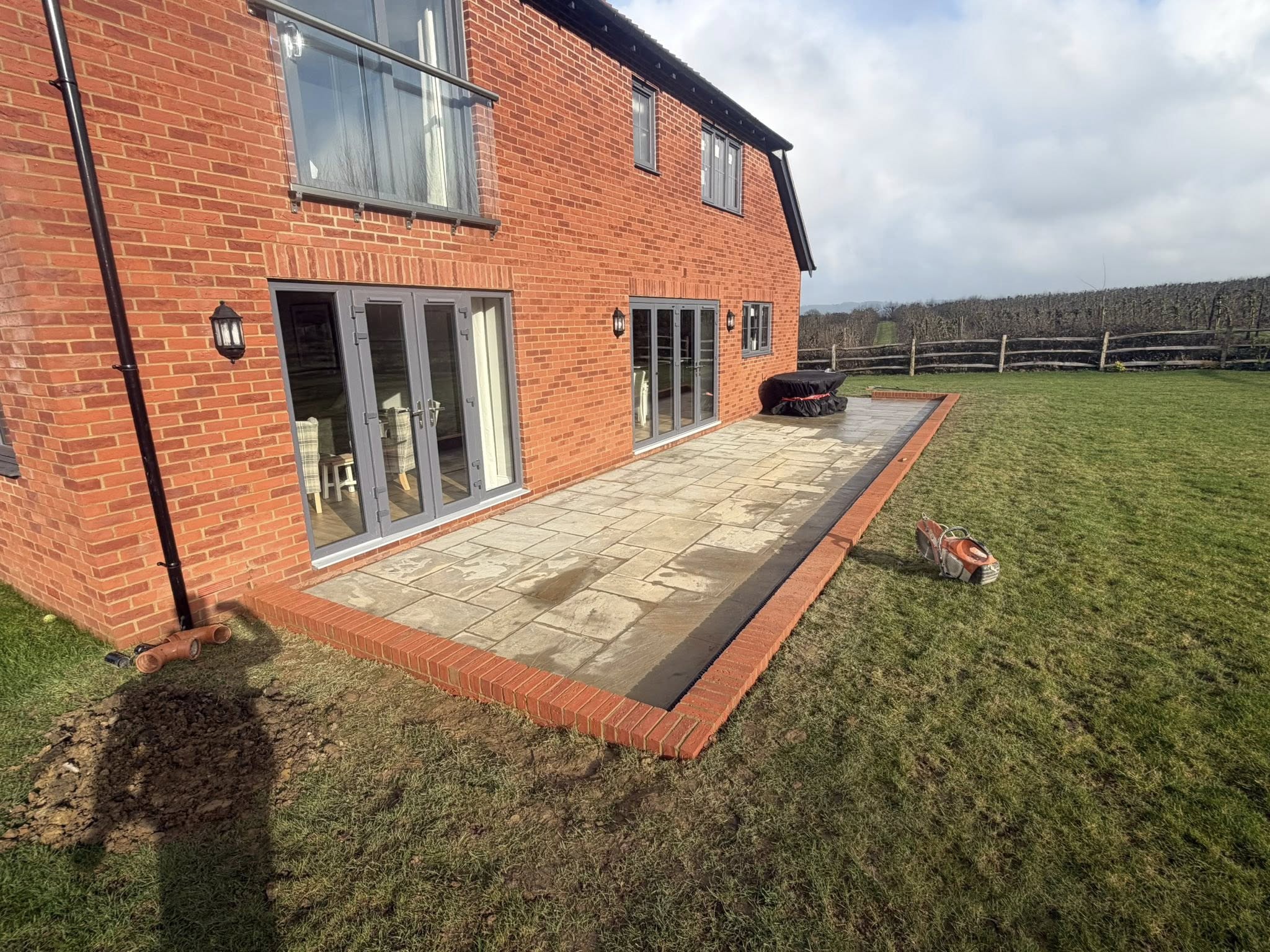
Where a newly leveled, retained earthen tier steps down directly into a premium pedestrian terrace zone, the earth retention wall must interface cleanly with the paving base layers. The subsurface drainage networks from the wall heel lines must route completely beneath the patio plates, ensuring that groundwater does not track into the bedding layers of adjacent luxury porcelain slabbing kent projects.
Furthermore, the patio edge must incorporate high-capacity linear slot drainage channels parallel to the retaining base to capture immediate face runoff sheets, routing water away before it can destabilize the paving subgrade.
+-----------------------------------------------------------------------+
|                    RETAINING WALL AND PATIO BOUNDARY HANDSHAKE        |
+-----------------------------------------------------------------------+
|                                                                       |
|   [ RETAINED UPPER GRADE ]                                            |
|   ========================                                            |
|   | GABION GRAVITY WALL  |                                            |
|   +----------------------+                                            |
|   |  HEEL PERF DRAIN RUN |                                            |
|   +----------------------+                                            |
|   ========== GROUND LEVEL INTERFACE ===============================   |
|              | LINEAR SLOT DRAIN | [ VITRIFIED PORCELAIN PATIO ]      |
|              +-------------------+ [ Laid over rigid 4:1 bed ]        |
|                                                                       |
+-----------------------------------------------------------------------+
Preserving Damp Proof Course Boundaries
Where structural earthworks cut close to existing residential brick leaves or newly constructed home extensions, the final grade elevations must respect statutory moisture boundaries. Building an earth bank or structural terrace platform that rests directly against an unprotected external brick leaf will bridge the property’s damp proof course line, causing immediate internal dampness tracking.
Where retention elements must border primary building skins, the masonry surfaces must be fully waterproofed using continuous tanking membranes and isolated by vertical drainage sheets.
All facing brickwork executions must conform exactly to premium historic brickwork repointing kent guidelines, ensuring that any adjacent retaining brick masonry leaves utilize frost-resistant materials and breathable joints to prevent localized salt scaling or moisture entrapment along the building boundary.
6. Comprehensive Operational Phased Lifecycle for Geotechnical Earth Retention
To ensure every geotechnical check, subgrade compaction pass, and hydraulic drainage line interfaces flawlessly throughout the construction loop, site management must enforce a strict, phased project timeline.
Phase 1: Site Surveys, Trial Pit Profiling, and Engineering Plan Checks
Before any heavy mechanical plant enters the workspace boundary, the structural ground parameters and layout dimensions must be fully checked and verified.
- Geotechnical Soil Testing: Dig out exploratory trial pits across the retention path to confirm California Bearing Ratio readings and check localized clay shrinkage properties.
- Utility Infrastructure Scanning: Scan the excavation footprint using high-sensitivity Ground Penetrating Radar (GPR) to map all buried main utility pipelines, power lines, and data conduits, establishing clear mechanical exclusion zones.
- Engineering Plan Validation: Secure formal Building Control plan check sign-offs for all reinforcement steel schedules, padstone details, and global factor of safety calculations.
Phase 2: Mass Excavation, Slope Shoring, and Foundation Base Compaction
This phase manages the physical cutting away of the terrain and constructs the unyielding structural foundation platforms.
- Bulk Embankment Excavations: Deploy heavy tracked excavators to clear away topsoils and cut out the design grades, building safe temporary slope batters or installing steel shoring shields to prevent sudden bank shear failures.
- Muck-Away Environmental Routing: Sort and load out all un-useable soil spoils into certified waste transport vehicles in compliance with regional environmental directives.
- Subgrade Platform Compaction: Grade the raw foundation beds to laser accuracy and compact the ground using heavy mechanical vibrating rollers until achieving maximum dry density.
Phase 3: Rebar Setting, Concrete Pours, and Drainage Integration
The core installation phase where the foundation anchors are cast and subsurface hydraulic relief paths are sealed into the backfill zone.
- Foundation Steel Construction: Assemble the high-tensile steel rebar grids inside robust timber shuttering frames, elevating the mesh cages on concrete spacer blocks to guarantee a fifty-millimeter concrete cover skin.
- Casting the Base Blocks: Pour high-density structural concrete into the formwork tracks in continuous volume streams, processing the wet matrix with mechanical poker vibrators to extract all entrapped air voids.
- Drainage Infrastructure Placement: Position the perforated twin-wall heel drainage pipes along the cured footing plates, build out the forty-millimeter angular aggregate column, and enclose the entire gravel structure inside its protective non-woven geotextile filtration sleeve.
Phase 4: Stem Construction, Backfill Compaction, and Handover Clearance
The final technical phase where the wall structure is built to its design height, backfilled, and signed off for final landscape integration.
- Stem Structural Assembly: Build out the vertical cantilever blockwork stem lines, or stack the Galfan-coated welded wire mesh gabion cages at the mandatory one-in-ten backward structural batter inclination, manually hand-packing the front facing stones.
- Controlled Backfill Layering: Introduce native soils behind the geotextile aggregate sleeve in controlled one-hundred-and-fifty-millimeter lifts, running mechanical compaction passes after each layer to eliminate future ground settlement risks.
- Final Alignment Audits and Handover: Execute a final comprehensive multi-axis laser check across the finished retention assets, verify that all louvered weep vents are free of mortar blockages, and formally sign off the asset for immediate landscaping integration.